About the Suzuki TU250x
 The Suzuki TU250x is a 249cc EFI UJM, produced in Japan and
imported for sale in the United States from 2009 to 2015. The
bi-yearly updates of the US version have thus far been limited to
trim-line changes.
The Suzuki TU250x is a 249cc EFI UJM, produced in Japan and
imported for sale in the United States from 2009 to 2015. The
bi-yearly updates of the US version have thus far been limited to
trim-line changes.
Outside of the US, the bike has a wider audience and has been available longer; originally as a carbureted, 4-valve format with more variants and options. The closest direct kin to the modern TU250X in the Japanese market is the ST250.
The ST250 was available in a standard model and an "E-Type" model. The E-Type is the fancier version, with a two-tone trim-line, and prior to 2008 a kickstarter and a decompression lever on the cylinder head cover. The kickstart feature was dropped from the E-Type line in 2008, along with a switch to fuel injection. Interestingly, the 2008 E-Type appears to be the basis for the 2009 TU250X (ie: the "fast red one").
I will use the following conventions when referring to models for the rest of this document:
- SP250
- 1982 or 1983 SP250 dual sport, carbureted 4 valve, with kickstart
- ST250
- 2004 or later ST250, carbureted 2 valve, no kickstart
- ST250XK4
- 2004 through 2007 ST250 E-Type, carbureted 2 valve, with kickstart
- ST250XK8
- 2008 or later ST250 E-Type, EFI 2 valve, no kickstart
- TU250X
- 2009 or later TU250x, EFI 2 valve, no kickstart
What's Missing for the Kickstart
The omission of the kickstart feature on the TU250X is accomplished partly by the expedient of simply not including the parts, and by plugging up the hole in the clutch cover. However, there is one important piece which is altered rather than left out: the drive shaft.
On the ST250XK4, the drive shaft has an elongated tail which projects out of the crank case. It is onto this nub that the idler gear would be set. On the TU250X, ST250, and ST250XK8 the shaft is too short to mount the gear (though oddly it retains a groove for the retaining clip).
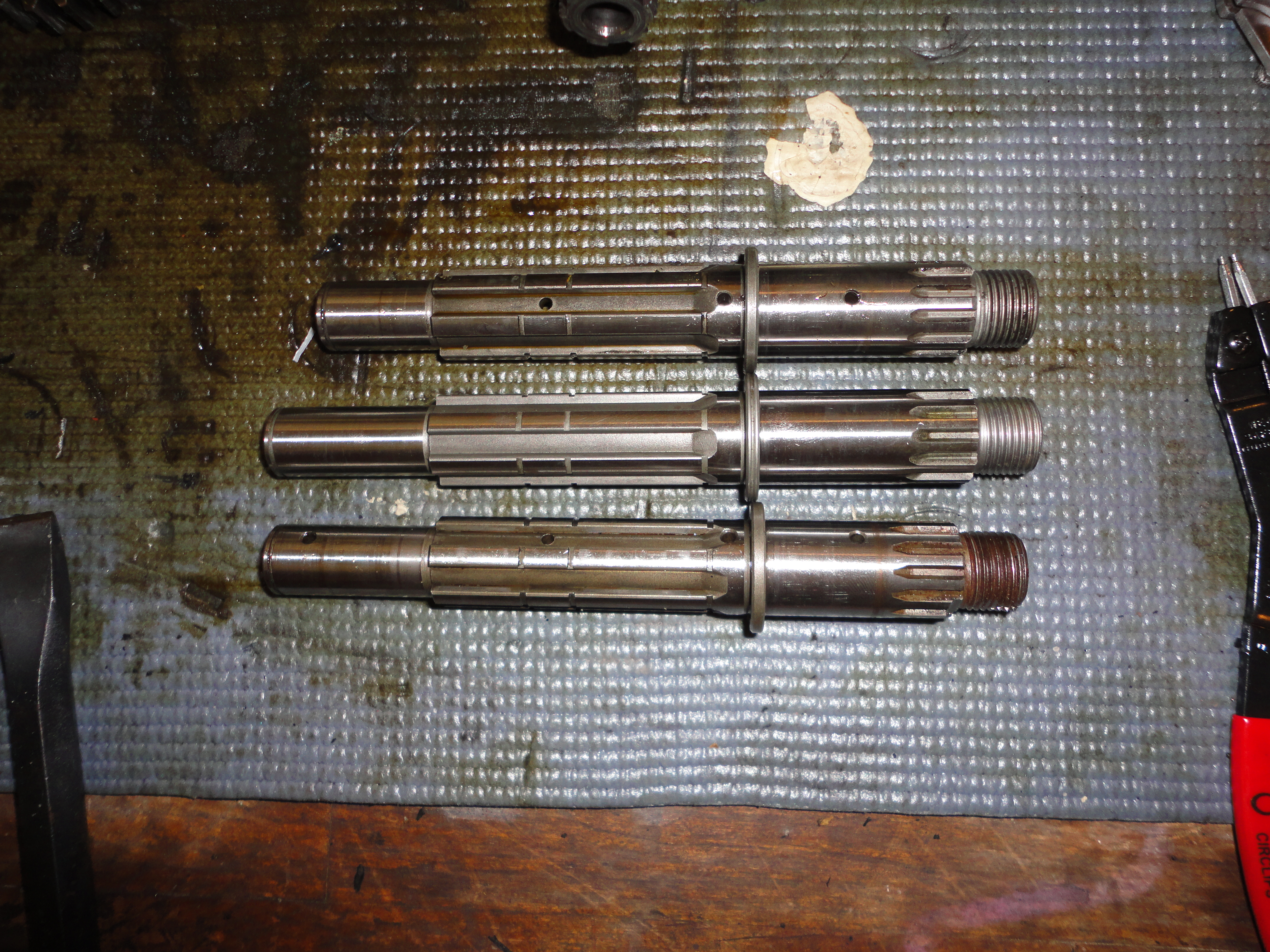 For reference here is the original TU250X drive shaft (top), the
ST250XK4 (middle), and the SP250 (bottom). Note that the older SP250
shaft does include the longer tail end to support the idler gear, but
that the sprocket end is shorter (possibly due to the SP250's narrower
frame).
For reference here is the original TU250X drive shaft (top), the
ST250XK4 (middle), and the SP250 (bottom). Note that the older SP250
shaft does include the longer tail end to support the idler gear, but
that the sprocket end is shorter (possibly due to the SP250's narrower
frame).
Getting Kickstart Parts
 The internal pieces of the actual kickstart assembly are identical to
those from the older SP250 incarnation of the this family of
engine. These assemblies can frequently be found on eBay
for under $50 USD, although the completeness of parts can be hit or
miss.
The internal pieces of the actual kickstart assembly are identical to
those from the older SP250 incarnation of the this family of
engine. These assemblies can frequently be found on eBay
for under $50 USD, although the completeness of parts can be hit or
miss.
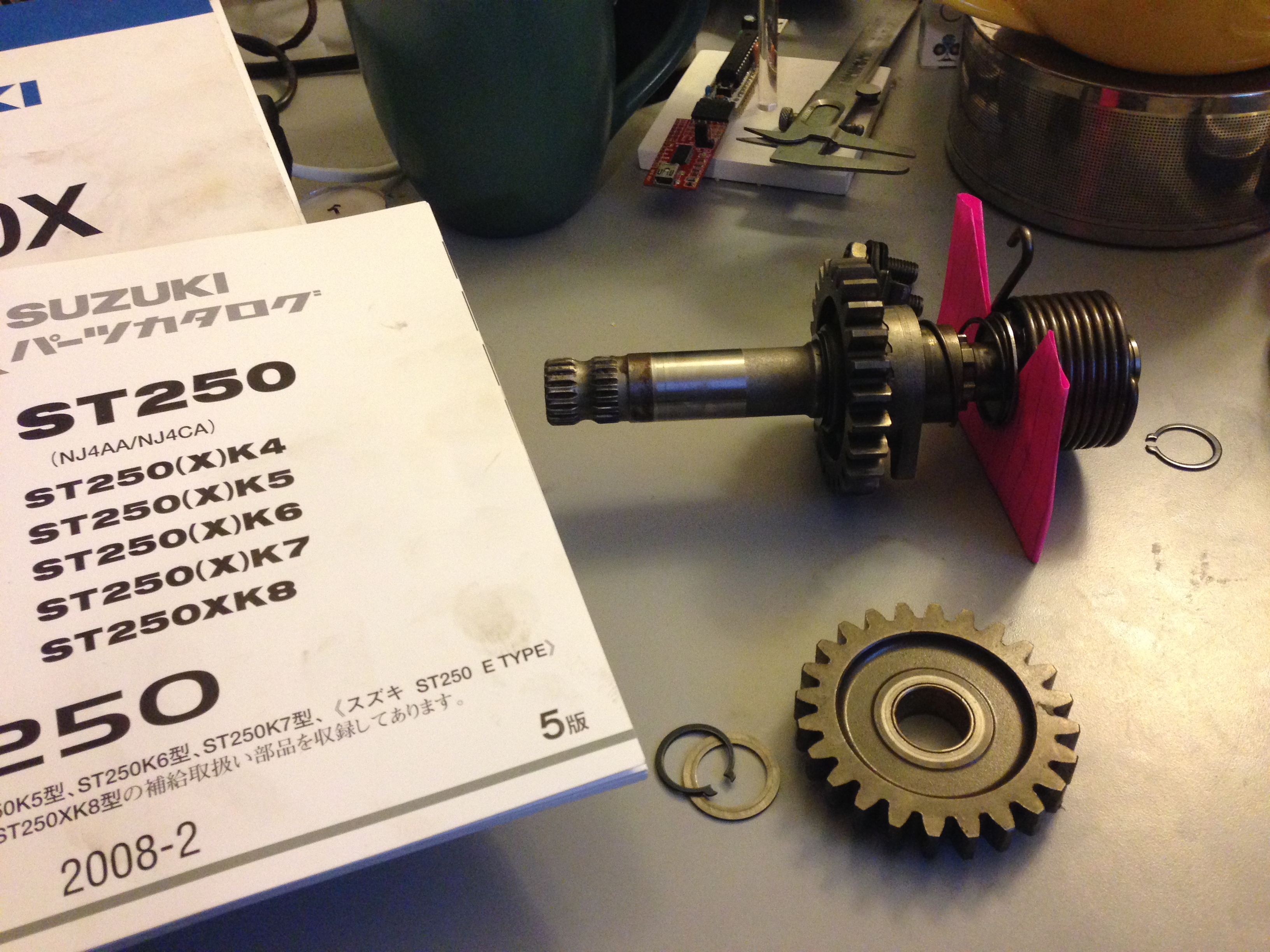
The idler gear (and its washer and circlip) can sometimes be had on eBay as well (even as part of an auction for the kickstart assembly mentioned above). Note that this gear is categorized as part of the transmission assembly in any of the Suzuki part list breakdowns.
The elongated driveshaft which is necessary for mounting the idler gear does not appear in any prior models available in the US.
You will need to find a new oil seal and the correct kickstart lever. The oil seal is available in the US, but the lever is not.
Note that the SP250's lever sweeps in a different arc than the ST250XK4's, which will very likely be an issue as the folded lever fits close to the motorcycle's frame. It would almost certainly come into contact with the frame, but I have not physically verified this.
There is an EMGO Suzuki kickstart lever
which looks like it will fit which does not fit. The teeth on the kickstart shaft attach point are the wrong size.
I had a good experience in obtaining the Japan-only parts from Samurider.com, and I highly recommend going to them first. Simply contact them with the part numbers referenced below, and they will reply to your inquiry with a quote.
A full parts list breakdown is available in the required parts section later in this document.
What's Missing for the Decomp
The decompression lever is part of the cylinder head assembly, specifically on the cylinder head cover. Apart from the small shaft and return spring of the decomp itself, there is a small hole that would be bored through the cover. On the non-E-type models, this hole is not present, though it is obvious where it would be bored out on the mold.
In order to add a decompression lever, one must acquire:
- decompression assembly
- supporting cylinder head cover (normally only sold as a unit with the cylinder head)
I weigh roughly 170 lbs with boots and gear and I am able -- without any prior skill in the matter -- to kick start my modified TU250X without the assistance of a decompression lever. At this time I have not sought out the necessary parts to add this feature. I may consider doing so in the future just for the sake of completeness. When/If that happens, I will update this guide to include the additional steps.
Prerequisites
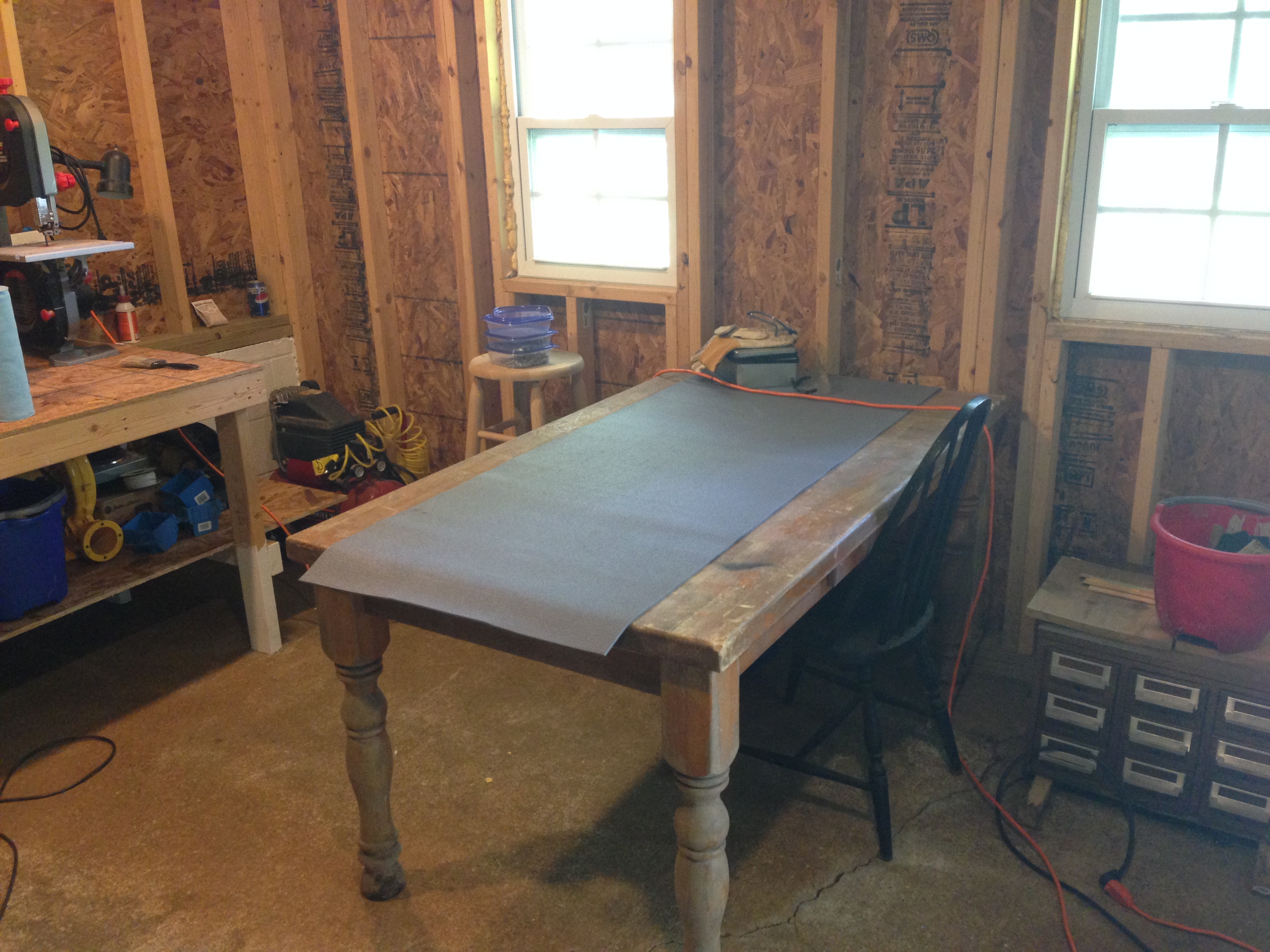 Before you even consider this modification, make sure you have the
time, space, and tools to bring it to completion. I was able to keep
the engine work constrained to a 3' x 5' table, with tools on a nearby
bench. Any smaller workspace may prove problematic.
Before you even consider this modification, make sure you have the
time, space, and tools to bring it to completion. I was able to keep
the engine work constrained to a 3' x 5' table, with tools on a nearby
bench. Any smaller workspace may prove problematic.
In the tools and
consumables sections that follow I include an
associate link to Amazon.com where applicable. If you can find the items
cheaper elsewhere, that's great! If you want to buy it from Amazon
though, please use these links. It won't cost you more, but I'll get a
nickel in my tip jar for having referred you. For the most part, I
tried to find the bast match to the tool I actually used, which may not
necessarily be the best one available.
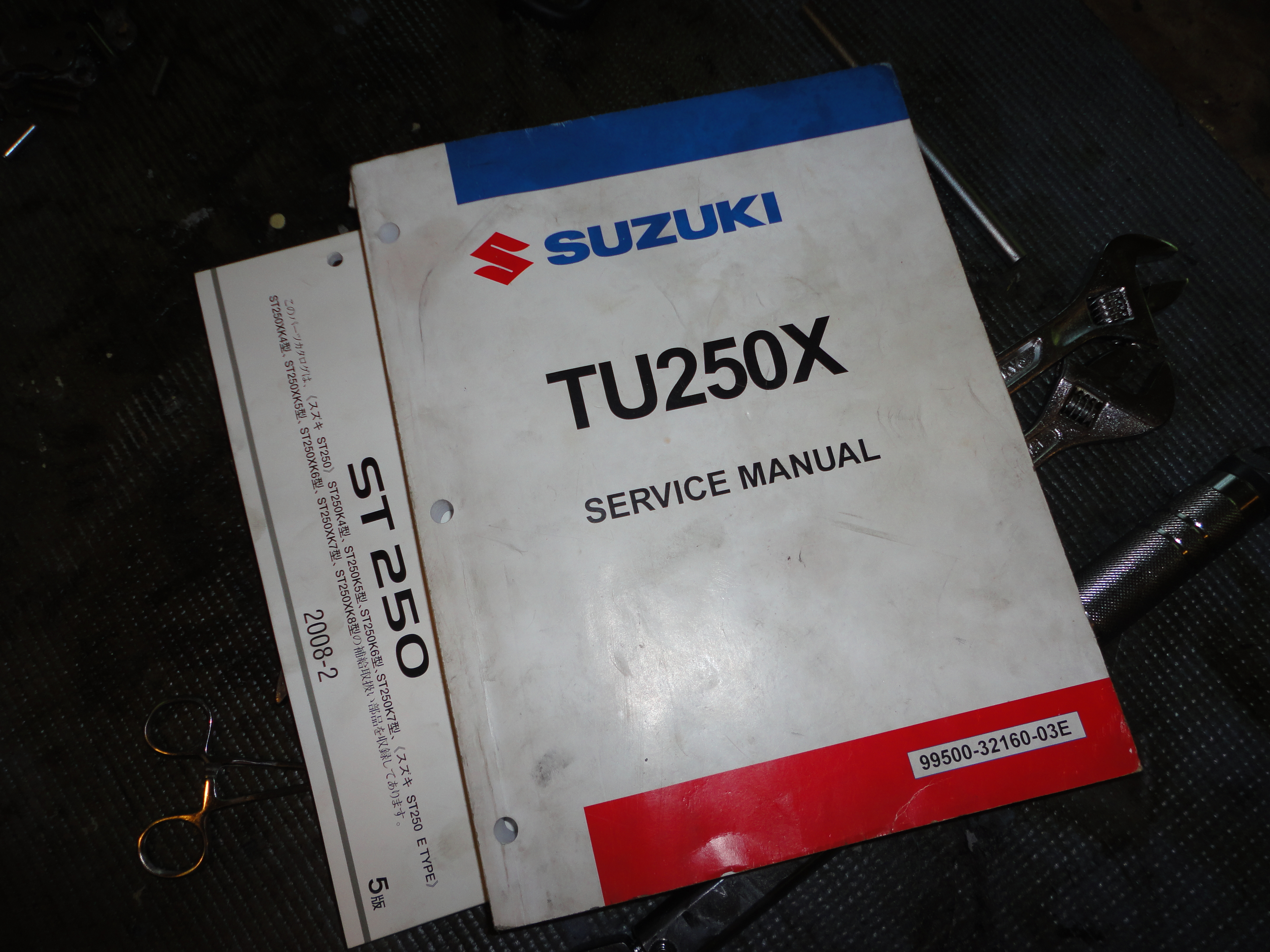 You will require a copy of the TU250X Service Manual, which
has step-by-step disassembly and re-assembly instructions, as well as
the correct torque values for all bolts and screws. I recommend
reading the engine disassembly and reassembly sections multiple times
in advance, so that you have a clear idea of what you'll be doing well
before starting the work. Even afterwards, keep it nearby as it's best
to double check your work against it as you progress.
You will require a copy of the TU250X Service Manual, which
has step-by-step disassembly and re-assembly instructions, as well as
the correct torque values for all bolts and screws. I recommend
reading the engine disassembly and reassembly sections multiple times
in advance, so that you have a clear idea of what you'll be doing well
before starting the work. Even afterwards, keep it nearby as it's best
to double check your work against it as you progress.
Required Parts
- Kickstart assembly
-
26211-38201Kickstart shaft09448-45008Return spring26221-32400Return spring guide08331-3117ASmall circlip08211-17341Spacer09440-32006Tension spring26231-38202Shaft drive gear26240-38200Shaft driven gear09181-22139(*2) Washer09380-22006(*2) Circlip26233-32400Return stopper26232-38200Return guide01500-08203(*2) Bolt09283-20031Oil seal26300-28D00Kickstart lever assembly (includes rubber and securing bolt)
- Transmission assembly
-
24130-38310Drive shaft26260-38200Idler gear09181-17130Spacer08331-3117ACirclip
- Gasket set
-
11482-38212Clutch cover gasket11483-37D11Generator cover gasket11241-26G00Cylinder gasket11141-26G00Cylinder head gasket
For reference, here are some parts diagrams of the kickstart and transmission assemblies where relevant.
- Kickstart Assembly
-
- SP250 - Parts Outlaw, Motosport, Bike Bandit
- ST250XK4 - Blurry Photo
- Transmission Assembly
-
- TU250X - Parts Outlaw, Motosport, Bike Bandit
- SP250 - Parts Outlaw, Motosport, Bike Bandit
- ST250XK4 - Blurry Photo 1, Blurry Photo 2
- Gaskets
-
- TU250X - Parts Outlaw, Motosport, Bike Bandit
Required Tools
- Rear stand
- For rear wheel removal, and as an aide in keeping the bike steady.
- Pneumatic jack
- To aide in engine removal and replacement. I didn't use a jack
specific to motorcycles, so I needed to use a piece of wood to
provide a relatively soft, flat surface between the jack and engine. - Powerbuilt 640181 Garage 2-Ton Trolley Jack
- Torque wrench
- It will need to be adjustable to at least 100 N/m for this project. - Neiko 3/8-Inch 10-80 Foot-Pounds Automatic Torque Wrench
- Breaker bar
- A lot of tough bolts, you'll need the leverage. - TEKTON 1703 1/2-Inch Drive x 25-Inch Flex Breaker Bar
- Impact driver
- In order to remove the four shift mechanism screws, which have
threadlock holding them in place. - Lisle 29200 3/8" Hand Impact Tool Set
- Case splitter
- This will pull the case halves apart. It functions by bolting into
the right side of the case and then applying a lot of pressure onto
the crank shaft. - Tusk Crankcase Splitter/Separator
- Clutch holder
- Acts as a handle so you can hold the primary driven assembly in
place. - Tusk Clutch Holding Tool
- Metric sockets
- 8mm, 9mm, 10mm, 12mm, 14mm, 17mm, 19mm, 24mm, 30mm
- Alan drivers
- You'll want actual socket drivers in order to get enough leverage to remove the cam sprocket bolts, which have threadlock.
- Circlip Pliers
- The transmission, kickstart assembly, and oil pump all use circlips
to retain their gears. - Lisle 49200 Heavy Duty Snap Ring Plier
Optional Tools
- Slide hammer/bearing puller
- I personally found one bearing that needed to be replaced. Removing
a bearing without a slide hammer and blind bearing puller approaches
impossible. You may not need this, if all your bearings spin freely. - 9pc Blind Hole Slide Hammer Pilot Bearing Internal External Remover Puller Set
- Rotor holder
- This is a specialty Suzuki tool specific for this task, but it's
possible to get around using it as the rotor bolt has significantly
more torque on it than many of the other bolts you'll be dealing
with. Suzuki part number
09930-44521 - Bar clamps
- Good for temporarily holding the case halves together when you are
in the process of digging out the baggie of case bolts. Four small
ones is enough. - Jorgensen 3706-HD 6-Inch Heavy-Duty Steel Bar Clamp
- Brass brush
- For cleaning mating surfaces and removing gasket bits. Brass is soft enough to not mar the aluminum of the engine. Do not use steel.
- Plastic razor/scraper
- For cutting away the side cover gaskets that inevitably adhere
themselves to the covers. Do not use regular razor blades, you run a
high risk of damaging mating surfaces and causing an oil leak. - Neiko 4-Piece Composite Scraper Set
- Leather work gloves
- The machined surfaces of the case are often sharp, and while you are trying to pull the case halves apart it is easy to slice yourself.
- Neoprene gloves
- Makes cleaning up for the night a lot easier. Especially useful if
you'll be doing the work in short spurts. - SAS Safety 66518 Raven Powder-Free Disposable Black Nitrile 6 Mil Gloves, Large, 100 Gloves by Weight
Required Consumables
- Assembly lube
- Any part that touches metal needs assembly lube. This stuff adheres
like a gel, but will dissolve in the engine oil once everything is
back together again. Lube liberally. - CRC SL3331 Extreme Pressure Engine Assembly Lube, 10 Wt Oz
- Liquid gasket 1215
- The case halves are machined to have a very tight mating
surface. Liquid gasket is applied in a very thin bead along the
specified surfaces (see your Service Guide) immediately prior to
joining the case back together. - THREE BOND GASKET MAKER GRAY 8.8 OZ TB1215
- Lithium grease
- Oil seals and frame bearings will want clean grease. - Liquid Wrench GR014 White Lithium Grease - 8 oz.
- Thread lock
- Required for the reassembly process, you really don't want your cam
nuts coming undone. - THREE BOND INT'L, INC. THREAD LOCK-MED/10ML 1333BT001
- Gasket set
- You'll need to replace the gaskets for the clutch cover, generator cover, cylinder, and cylinder head during the tear-down and rebuild process. See previous section for part numbers.
Optional Consumables
- WD-40
- For cleaning components prior to re-lubing them - WD-40 110071 Multi-Use Product Spray with Smart Straw, 11 oz. (Pack of 1)
- Gasket remover
- Wasting time on tough gasket remnants sucks, just
spray this on them and peel them off like a potato skin with the
plastic razor. - CRC 05021 Technician Grade Gasket Remover - 12 Wt Oz.
- Gallon baggies
- Put every assembly and various groups of screws in their own bags
- Shop towels
- There will be a lot of oil, grease, and general chemical gunk,
you're going to want something stronger than the paper towels in
your kitchen. Get the blue disposable shop towels. - SCOTT- Shop Towels, 12 rolls
- Oven cleaner
- I found that my cylinder head was encrusted with carbon deposits, as was my piston head. Oven cleaner, a brass brush, and a lot of elbow grease will help to remove it. I just had some dollar-stuff around, you're on your own here.
Remove the engine
To begin with, you'll be removing the easily accessible parts. Remove the side covers, seats, and gas tank. Remove the front sprocket. Remove the muffler, the oxygen sensor, and the exhaust header. Remove the starter motor. Remove the PAIR valve. Disconnect the throttle body from the cylinder head.
Unplug the generator, neutral detector, and temperature sensor cables. Disentangle those generator and neutral wires from the frame; they will be coming out with the engine and you don't want them catching on anything while you're focused on getting the engine out of the frame itself.
Drain the engine of its oil. Remove the oil pan and the shift detente from the bottom of the engine. This should give you a nice flat base to deal with, free from bolts.
Set the bike up on the rear stand. Note, I do this after all the easily accessible bits prior, especially the muffler -- my rearstand bumps into it, unnecessarily complicating things.
Remove the rear wheel. Set aside the rear axle bolt.
Set the pneumatic jack beneath the engine (use a flat of wood to protect the engine) and raise it to be firmly against the bottom, without accidentally knocking your bike off the rearstand.
Remove the five top and front mounting bolts, and the small bolt hiding underneath the swingarm frame bolt.
Remove the nut from the swingarm bolt, and use the rear axle bolt (which is conveniently the same size) to begin pushing the swingarm bolt out. This part is tricky. You want to get to the point where both bolts are holding one side of the swingarm to the frame, but where neither are preventing the engine from coming out.
Slowly, and very carefully, move the engine forward out of the frame and downward. This will take a lot of finesse and fidgeting, do not rush it and try not to lose your temper or your grip on the precariously balanced engine. More than any other aspect, this activity benefits from an assistant.
Leave the two bolts in place on either arm of the swingarm assembly. There are seals and covers that you risk having fall out or becoming misaligned if you don't have a bolt running through them.
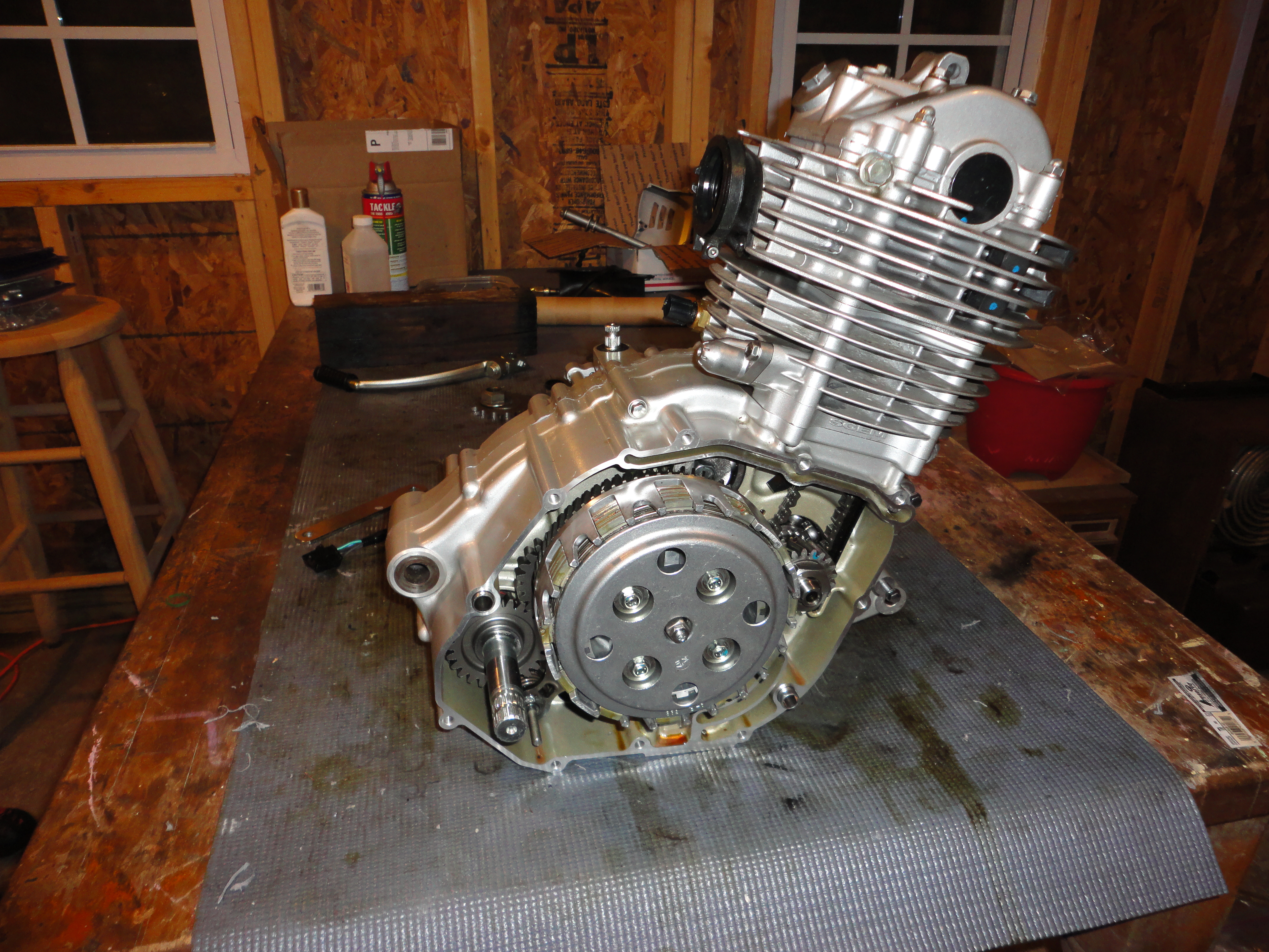
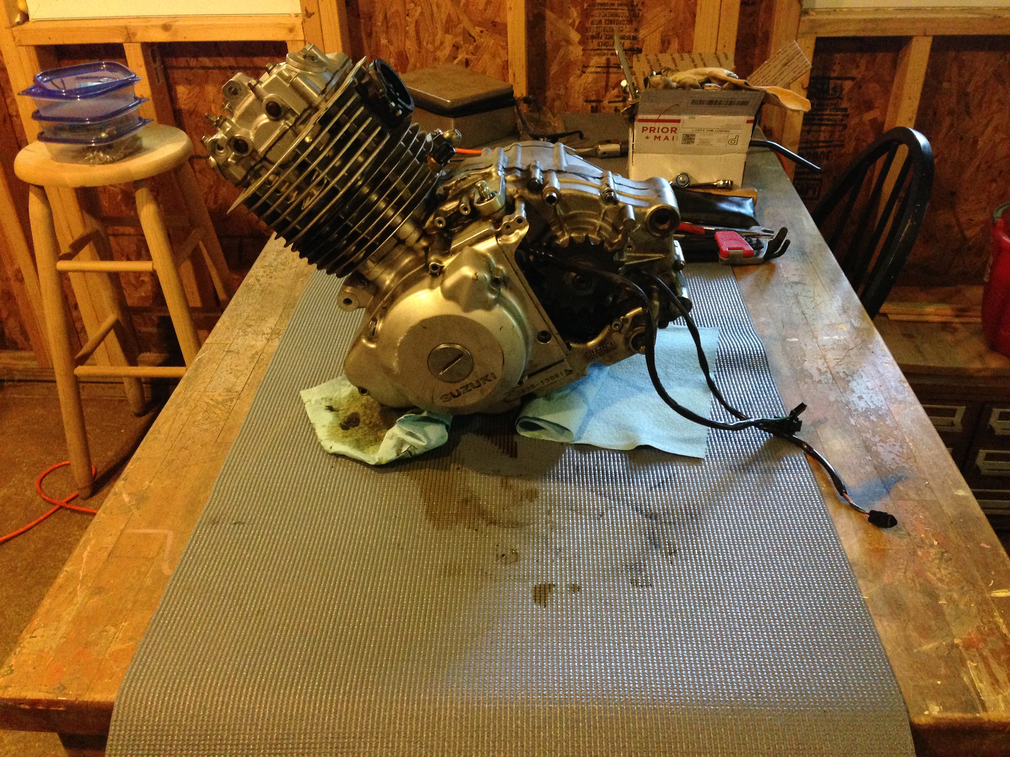 If all goes well, you can now lug around the 70 lbs of filthy and
unwieldy engine to your workspace. Again, I recommend at least a 3' by
5' table to perform this work on, and optionally some sort of durable
tablecloth or pad to deal with the mess. I, for example, finally got
some use out of a yoga mat I've had sitting around.
If all goes well, you can now lug around the 70 lbs of filthy and
unwieldy engine to your workspace. Again, I recommend at least a 3' by
5' table to perform this work on, and optionally some sort of durable
tablecloth or pad to deal with the mess. I, for example, finally got
some use out of a yoga mat I've had sitting around.
Disassemble According to Service Manual
There are a number of steps in the service manual that are geared more towards a full teardown. Since we are only interested in getting into the crank case, you can skip the removal of the generator rotor, removal of the piston, and removal of the crank shaft. You can also skip a full teardown of the cylinder head cover or removal of the valves.
Everything on the clutch-cover side of the engine must be removed, since that's the side of the crank case that you'll be sliding off and attaching the kickstart assembly to. Take special care with the mechanism of the gear shift assembly. Once freed of the gear selector drum, the spring-loaded pawls will eject themselves. Be prepared to grab and baggie them for later. Double check that you have both pawls, both pins, and both springs in the set.
 When separating the case halves with the case splitting tool, remember
that the case needs to come off straight or not at all. In my
particular situation, the counter-balance shaft was very tight in its
bearing, and came up with the case rather than falling out. This meant
that the counter-balance weight itself had to be maneuvered around the
crank. Be very patient.
When separating the case halves with the case splitting tool, remember
that the case needs to come off straight or not at all. In my
particular situation, the counter-balance shaft was very tight in its
bearing, and came up with the case rather than falling out. This meant
that the counter-balance weight itself had to be maneuvered around the
crank. Be very patient.
After separating, you'll need to clean off the old gasket material. The case gasket is a rubber substance which comes off easily with the sharp plastic scrapers. Take care that gasket remnants do not fall into the engine bearings, etc. You don't want tiny bits of rubber interfering with your engine after you've got everything re-assembled.
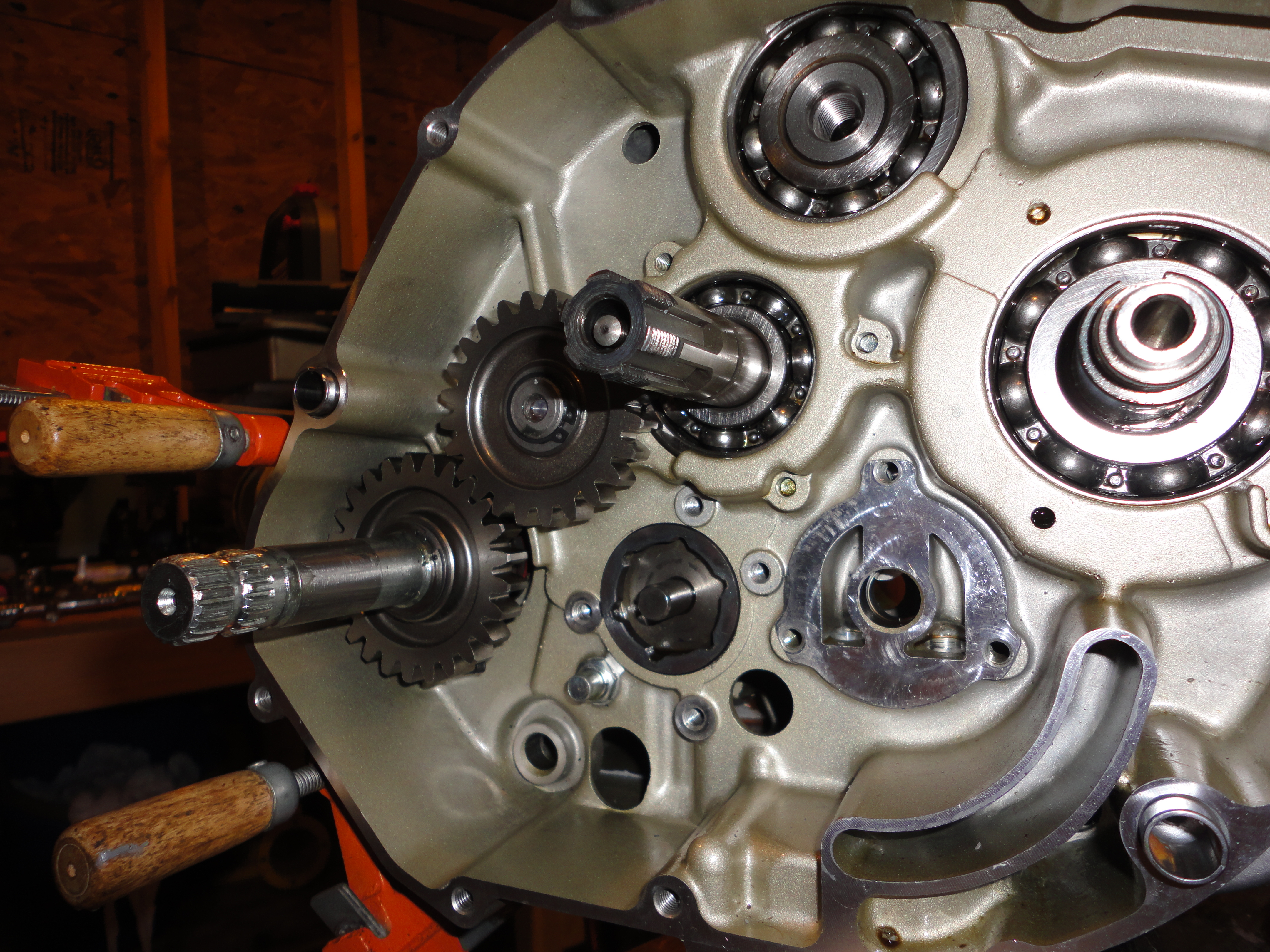
Replace driveshaft
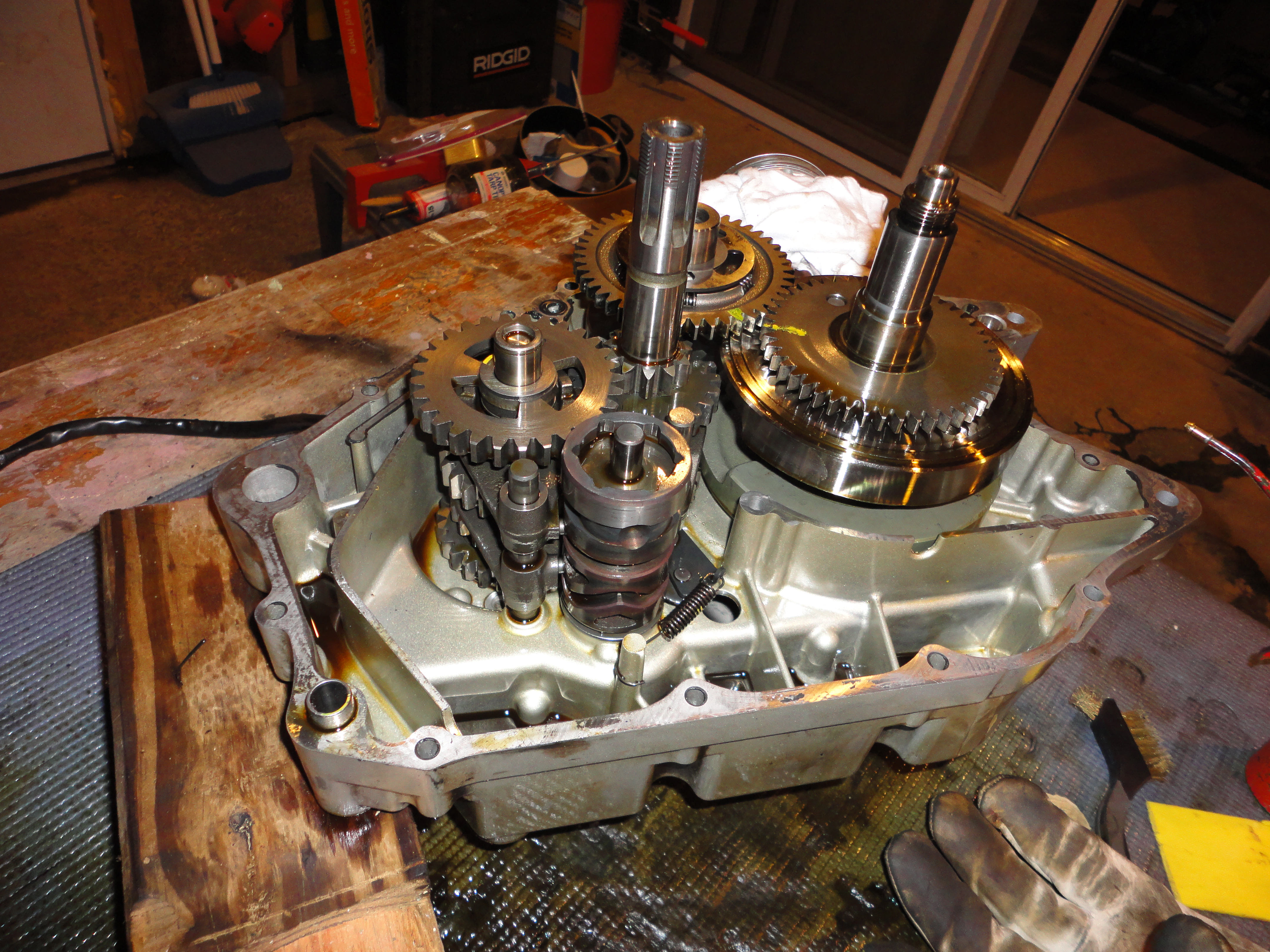
Pull the rails out of the gearshift forks, and then remove the gearshift drum. This should free up the countershaft and driveshaft of the transmission for removal. They will come out exactly straight and as a pair or not at all. You may find it helps to tap the driveshaft's sprocket mount with a rubber mallet to get things moving. Once again, the keyword here is patience.
This is a good time to verify that all of your bearings are turning freely. They should spin easily with just a light flick of your fingertip. In my case, I found that the countershaft bearing on the left case half (where the clutch actuator flipper sits) was resistant to turning, so had to pull and replace it. You'll need a slide hammer and blind bearing puller in this case -- see the optional tools section above.
At this point you can disassemble the driveshaft portion of the transmission. Smear assembly lube onto the longer ST250XK4 driveshaft, and assemble the original gears onto it. Pay careful attention to the orientation of your gears and the width of the washers. Refer to your service manual to double-check.
Install Kickstart Shaft
The kickstart shaft mounts through the right side of the crank case, just above the hole for the shift lever rod.
Lubricate the kickstart shaft, and install the smaller sliding ratchet gear onto it. Take care to line up the small dots that are impressed upon the shaft and the gear. Follow this with the tension spring and its large washer. The shaft can then be slid through the case where we will continue on the other side.
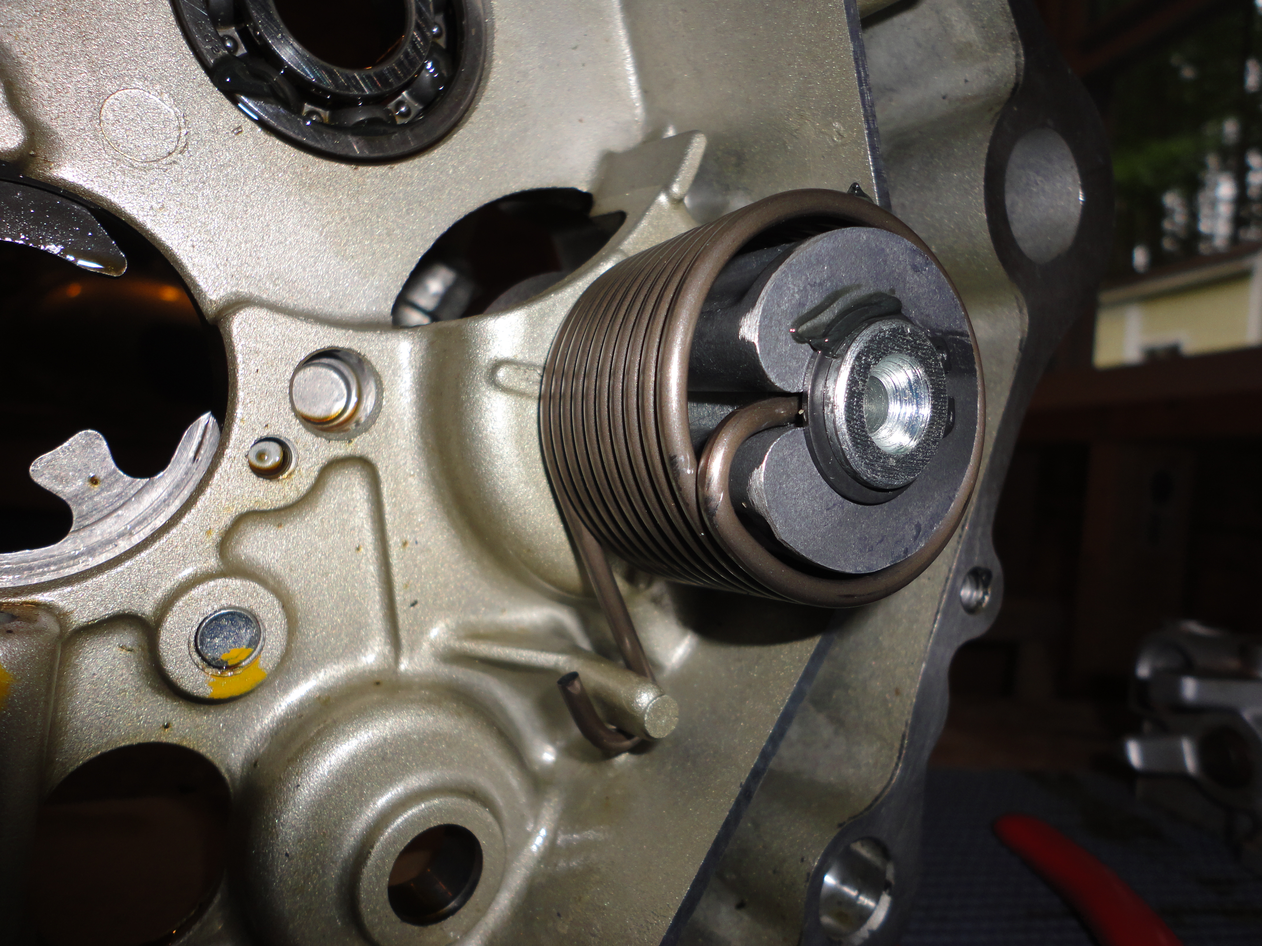 From the inside face of the right crank case, attach the return spring
to the case and through the hole in the kickstart shaft. Set the
spring guide into the spring with the angular end facing out. If the
guide is installed backwards (with the curved end facing out) the
spring may escape the guide. Install the circlip to retain the
guide. At this point, there should not yet be any tension on the
return spring.
From the inside face of the right crank case, attach the return spring
to the case and through the hole in the kickstart shaft. Set the
spring guide into the spring with the angular end facing out. If the
guide is installed backwards (with the curved end facing out) the
spring may escape the guide. Install the circlip to retain the
guide. At this point, there should not yet be any tension on the
return spring.
 Temporarily attach the kickstart lever onto the kickstart shaft,
pointing towards roughly 3 o'clock. With your left hand, rotate the
shaft counter clock wise, which will put tension onto the return
spring and rotate the sliding gear's guide into its correct "home"
position. At this position, hold the lever in place and attach the
stopper and guide plates by bolting them to the crank case. You can
then slowly relax your hold on the lever, allowing the sliding gear to
engage the the guide plate and come to rest pressing itself against
the stopper plate.
Temporarily attach the kickstart lever onto the kickstart shaft,
pointing towards roughly 3 o'clock. With your left hand, rotate the
shaft counter clock wise, which will put tension onto the return
spring and rotate the sliding gear's guide into its correct "home"
position. At this position, hold the lever in place and attach the
stopper and guide plates by bolting them to the crank case. You can
then slowly relax your hold on the lever, allowing the sliding gear to
engage the the guide plate and come to rest pressing itself against
the stopper plate.
I found this method to be significantly easier to manage than the documented one of attaching the guide and stopper plates first and attempting to put a quarter turn of tension onto the return spring using pliers before installing the return spring guide. I hope that it saves you some frustration as well.
 Verify that the shaft rotates cleanly, with the sliding gear moving
into and out of an engaged position and with the shaft returning and
stopping at the home position. If everything works, remove one of the
plate bolts, apply a drop of 1333 thread lock, and replace it. Then
repeat with the other bolt.
Verify that the shaft rotates cleanly, with the sliding gear moving
into and out of an engaged position and with the shaft returning and
stopping at the home position. If everything works, remove one of the
plate bolts, apply a drop of 1333 thread lock, and replace it. Then
repeat with the other bolt.
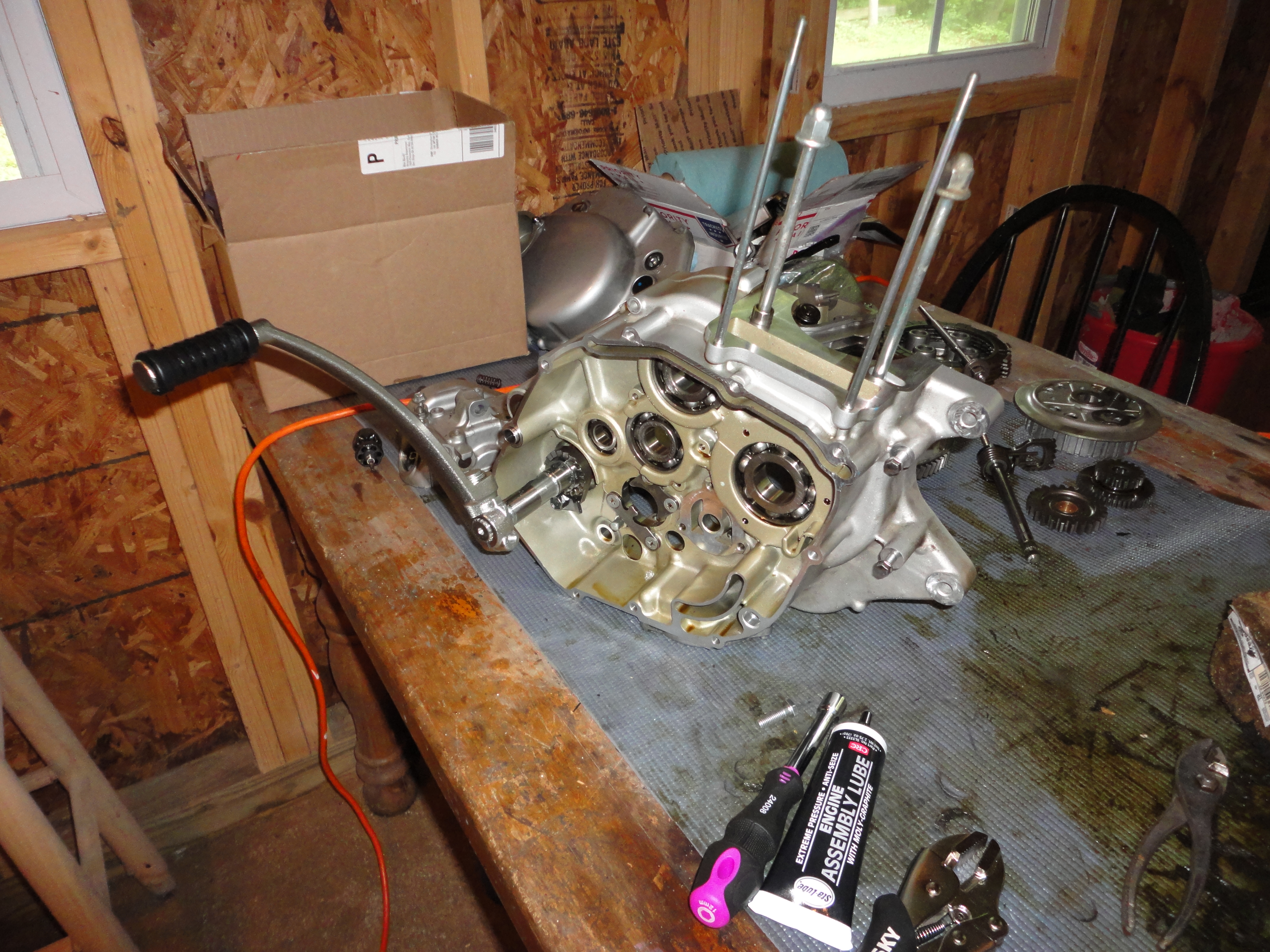
Close Up the Crank Case
You can now re-assemble the crank-case contents as per the service manual. If you find that some of the shafts are very tight, I recommend bagging the assembly in question and sticking it in the freezer for a few hours. This will cause a minute amount of metal shrinkage, which is often just enough to make the shafts not bind when you attempt re-assembly. As I'd mentioned earlier, the counter-balance was a tough fit when warm, but when cold I was able to get the case halves together without an issue. This is important, because you only have so much time to fiddle with getting the halves back together again after you've applied the liquid gasket.
Double check that everything is in place, that everything rotates as it should, that the crank and counter-balancer dots line up.
Apply a thin and even bead of liquid gasket to the surfaces indicated in the service manual and carefully join your case halves together. Once again, it goes on straight or not at all. As soon as you have the case surfaces mated, clamp them tightly together and start replacing all thirteen case bolts.
The case bolts are a variety of lengths. An easy rule of thumb to determine that you're using the correct bolt in a particular hole is to simply check that it has a between 1 and 2 cm sticking out if you insert it without turning. If you can insert it flush, it's obviously too short of a bolt; if it only slides in a bit and leaves more than 2cm sticking out, then it's too long.
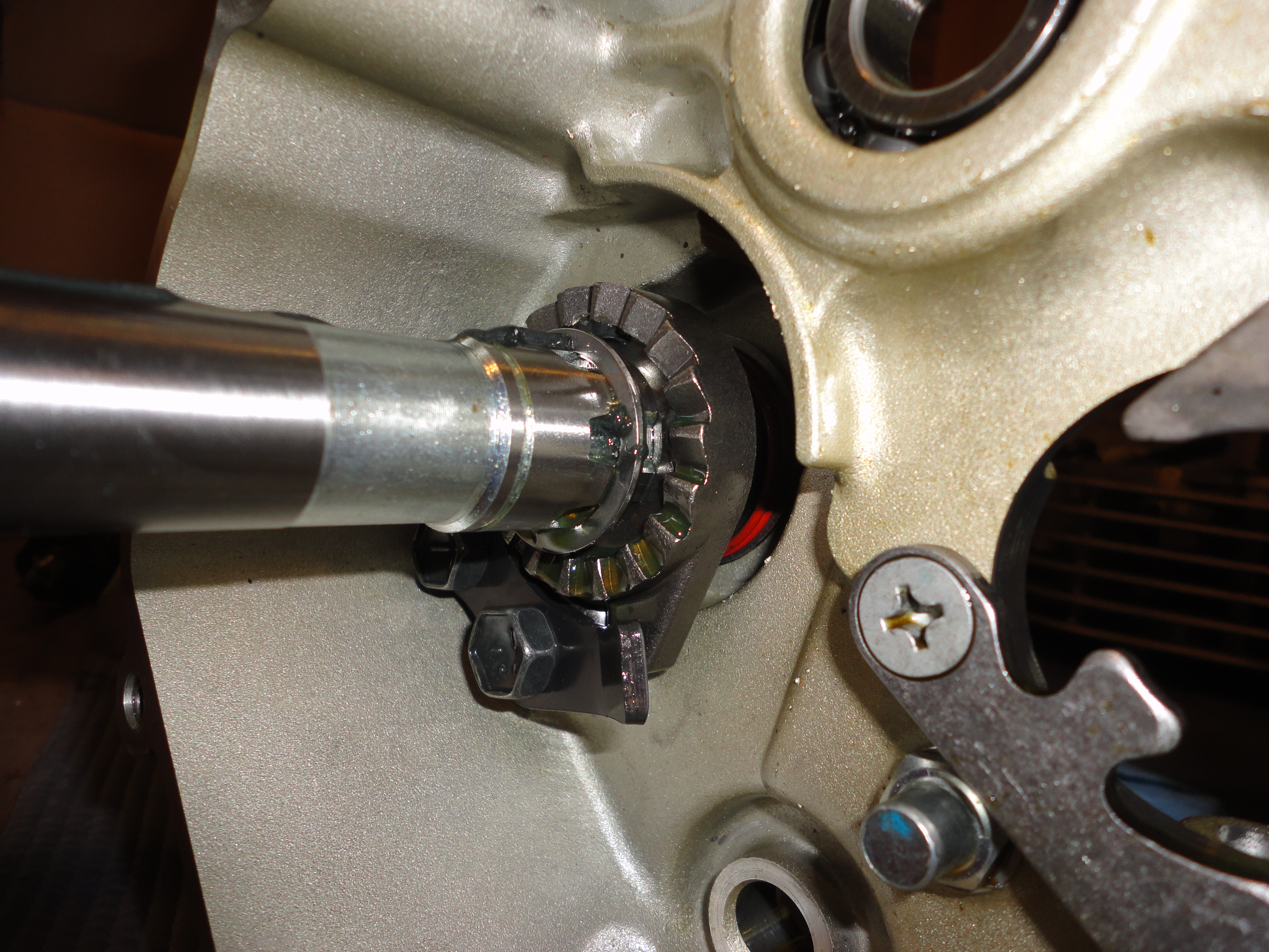
Install Idler and Complete Kickstart
While your seal is setting up, you can install that idler gear onto the newly elongated nub of your drive shaft. Lube up and slide on the gear, the spacer, and attach the circlip. Check that it spins freely and doesn't wobble.
Moving on to the kickstart shaft, you can now install a circlip and washer, then the larger part of the kickstart gear pair. It should mesh with the idler. Another washer then a final circlip to hold it in place.
 The idler and kickstart gear should spin freely, without encountering
the ratcheting teeth of the sliding kickstart gear that is held away
by the guide plate. When the kickstart shaft is turned counter clock
wise, the sliding gear will leave the guide plate and will slide out
to engage with the teeth of the kickstart gear, in turn driving the
idler.
The idler and kickstart gear should spin freely, without encountering
the ratcheting teeth of the sliding kickstart gear that is held away
by the guide plate. When the kickstart shaft is turned counter clock
wise, the sliding gear will leave the guide plate and will slide out
to engage with the teeth of the kickstart gear, in turn driving the
idler.
Now is a good time to take a flat-faced drift or old screwdriver and knock the kickstart plug out of the clutch-cover and replace it with the proper oil seal. The plug is in there pretty well, so smack it firmly from the inside of the case, dead center on the plug itself. Take care not to accidentally gouge your cover. Once the plug pops out, the oil seal can be placed with only finger pressure and some patience. The opening through which you can see the tension spring should face into the engine, not out. Make sure it fully seated, and lube it up with some lithium grease.
Put It All Back Where You Found It
 If this all goes smoothly, then you're in the clear to complete the
re-assembly process. Follow the service guide, and everything should
fit together. Make sure all your mating surfaces are clean before
placing new gaskets. I had a real bastard of a time removing the old
clutch cover gasket chunks, and it took a lot of CRC gasket remover
and elbow grease with a plastic razor before I could call it
ready. But all that work sure beats having an oil leak later.
If this all goes smoothly, then you're in the clear to complete the
re-assembly process. Follow the service guide, and everything should
fit together. Make sure all your mating surfaces are clean before
placing new gaskets. I had a real bastard of a time removing the old
clutch cover gasket chunks, and it took a lot of CRC gasket remover
and elbow grease with a plastic razor before I could call it
ready. But all that work sure beats having an oil leak later.
Remount the engine by lifting it slowly with the pneumatic jack, and turning, twisting, and guiding it into place. I focused first on getting the swingarm mount lined up, and drove home that bolt before trying to line up any others. As you push the swingarm mount bolt through, it will force the rear axle bolt back out.
After the engine is secure, it's time to reconnect the cables, re-install the rear wheel, the chain, the front-sprocket, and everything else you removed in the first place.
If you wanted to remove your PAIR valve, this is the perfect opportunity -- just skip re-installing it and patch up the three connection points that need filling. For more information, visit my PAIR removal page.
Put in a new oil filter, replace the shift neutral stopper, oil pan, and drain plug, and fill her up with clean oil. Double check all of your mounting bolts and available case bolts for their proper torque. Check that while you were doing this, no oil has been pouring out of the engine.
Slide on the kickstart lever, and bolt it securely in place.
Start That TU
Look over everything once more. What did you forget? I always forget something, and this is the time to remember it!
Try the electric start first, and holler like a madman when it fires up. Calm your neighbors, reassuring them that you aren't hurt, you're just very happy. Shut off the engine, and attempt to kick your TU into life!
 It may take you a while to get the hang of it, but don't
be discouraged. The fuel pump will sporadically start whenever you
turn the engine even slightly, just ignore it and give the lever a
good strong kick back and down. I find it helps to grab the front
brake lever along with the clutch, and push back on the bars a
bit. After a weekend of riding and starting it by kick, you'll get the
feel for it!
It may take you a while to get the hang of it, but don't
be discouraged. The fuel pump will sporadically start whenever you
turn the engine even slightly, just ignore it and give the lever a
good strong kick back and down. I find it helps to grab the front
brake lever along with the clutch, and push back on the bars a
bit. After a weekend of riding and starting it by kick, you'll get the
feel for it!
Congratulations, ride safe, and have fun!
Change log
- 2023-09-24: Update to local photos since picasa is dead and gone
- 2015-11-11: Remove mention of EMGO lever, it does NOT work.
- 2014-09-16: Spell checking.
- 2014-08-29: Corrected circlip pliers suggested item -- it was too big for the holes on the clips suzuki uses.
- 2014-08-26: Mention the EMGO kickstart lever which may work. Added more Amazon links.
- 2014-08-25: Re-read and found all sorts of terrible wording and bad grammar. Added some product links, with more to come later.
- 2014-08-19: Initial published revision. Need to add Amazon links for the various tools and consumables.
- 2014-07-27: Draft layout.