About the Suzuki TU250x
 The Suzuki TU250x is a 249cc EFI UJM, produced in Japan and
imported for sale in the United States from 2009 to 2015. It is a very
clean and efficient machine -- I personally have achieved an average
of 72 mpg since I bought mine in April of 2013. It meets stringent EPA
guidelines... with the exception of the venting on the gas tank's cap
which prevents it from being sold as new in the state of California.
The Suzuki TU250x is a 249cc EFI UJM, produced in Japan and
imported for sale in the United States from 2009 to 2015. It is a very
clean and efficient machine -- I personally have achieved an average
of 72 mpg since I bought mine in April of 2013. It meets stringent EPA
guidelines... with the exception of the venting on the gas tank's cap
which prevents it from being sold as new in the state of California.
About the PAIR System
Pulsed Secondary Air Injection is a system whereby clean air from the airbox of the motorcycle is allowed to be sucked into the exhaust valve during a low pressure wave.
It's a two-part emissions system. On one hand, it's mixing clean air into the exhaust header prior to any kind of measurement being taken. On the other, this clean air does allow unspent fuel to be burned before it leaves the exhaust system.
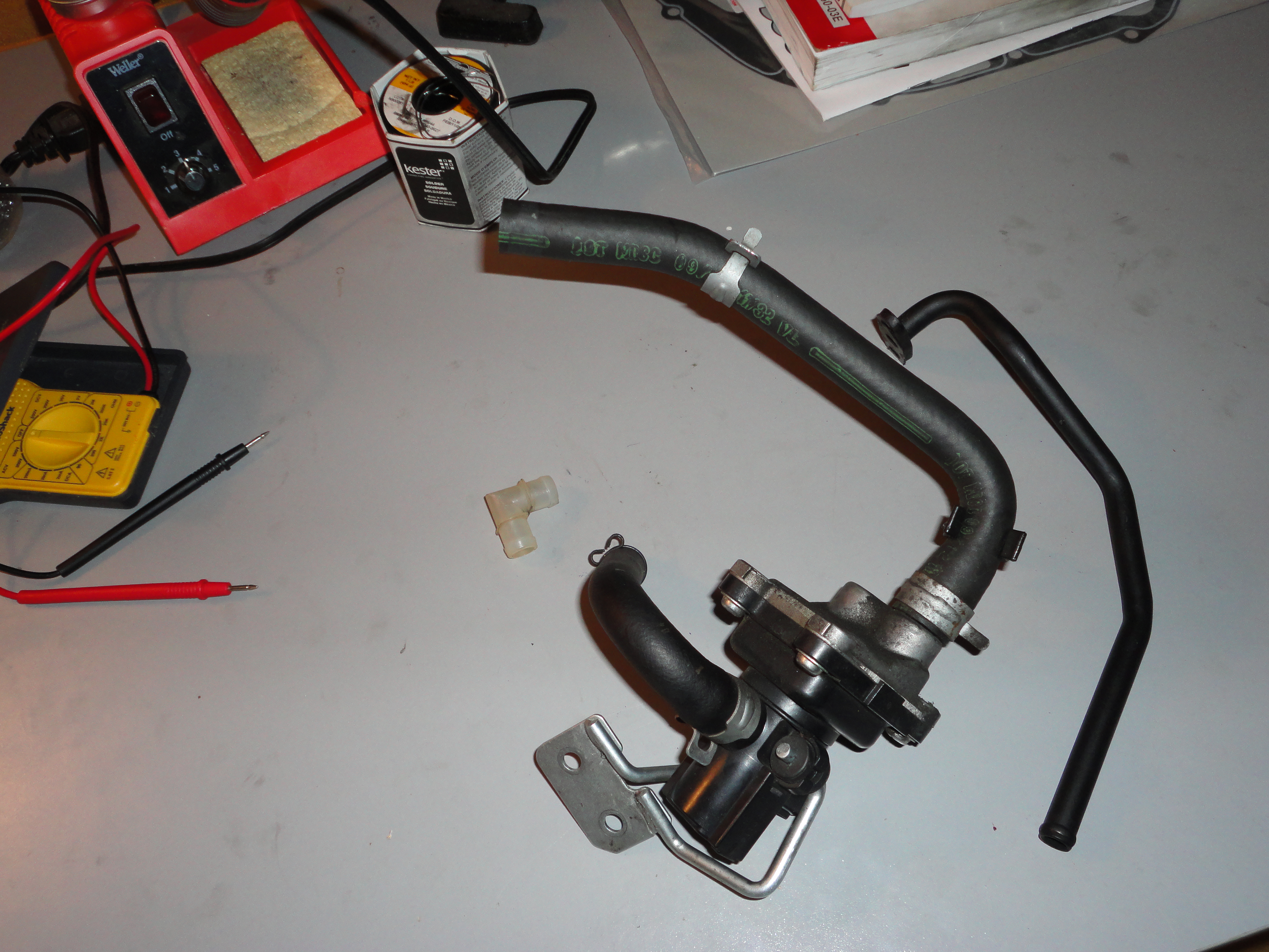
The PAIR valve on a Suzuki has a one-way reed valve which ensures that no exhaust pressure pushes its way into the air box, and a solenoid-driven valve which disables the flow entirely in either direction.
If the ECU detects that the PAIR solenoid is not electrically connected, it will set an error state and cause the FI light to come on.
The reed valve needs to be cleaned periodically, as it gets caked with carbon buildup from the exhaust gasses. Eventually it will no longer operate correctly, but the ECU will not be able to see the problem.
Why Would I Remove the PAIR System
 The device does not weigh much, and only draws on the battery in brief
burts at idle RPMs. It is however a tangle of tubes and wires that I
found myself having to fight with during the disassembly process, and
which I was not interested in replacing
during reassembly. There is no discernable performance
increase. The engine does look less cluttered, from a visual appeal
perspective.
The device does not weigh much, and only draws on the battery in brief
burts at idle RPMs. It is however a tangle of tubes and wires that I
found myself having to fight with during the disassembly process, and
which I was not interested in replacing
during reassembly. There is no discernable performance
increase. The engine does look less cluttered, from a visual appeal
perspective.
Patching Things Up
Leaving the PAIR valve out (or removing it) leaves three points in need of patching.
- The air box needs to be plugged where it would have fed into the PAIR valve. Technically the hole is on the rubber tube connecting the air box to the throttle body, but "air box" is easier.
- The exhaust side of the cylinder head cover needs a blank covering the hole where it would have been fed by the PAIR valve
- The ECU needs to have a voltage available on its PAIR enable pin to trick it into behaving as if the PAIR valve were still intact.
Plug Up the Air Box
Here is a diagram of the air cleaner on the TU250x. We'll
be replacing the part labelled 5 (air cleaner joint, 13858-14D20)
with a plug of some variety.
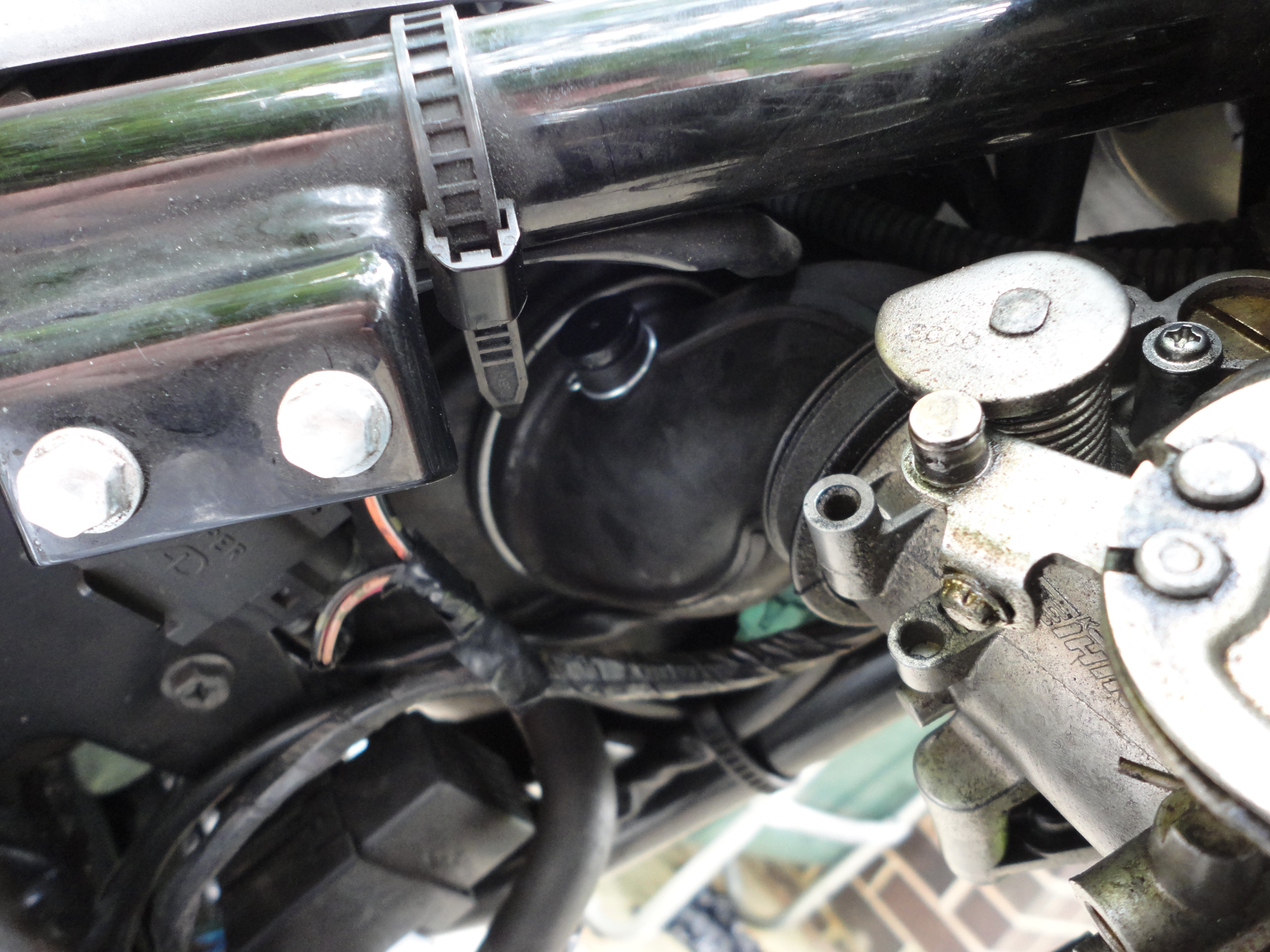 This is the easiest to patch. Any plug that fits will do, as only
negative pressure will be occurring at this location. If you leave
this spot unplugged it will act like a bypass of the air filter, and
air will be drawn through it and into the throttle body without being
filtered.
This is the easiest to patch. Any plug that fits will do, as only
negative pressure will be occurring at this location. If you leave
this spot unplugged it will act like a bypass of the air filter, and
air will be drawn through it and into the throttle body without being
filtered.
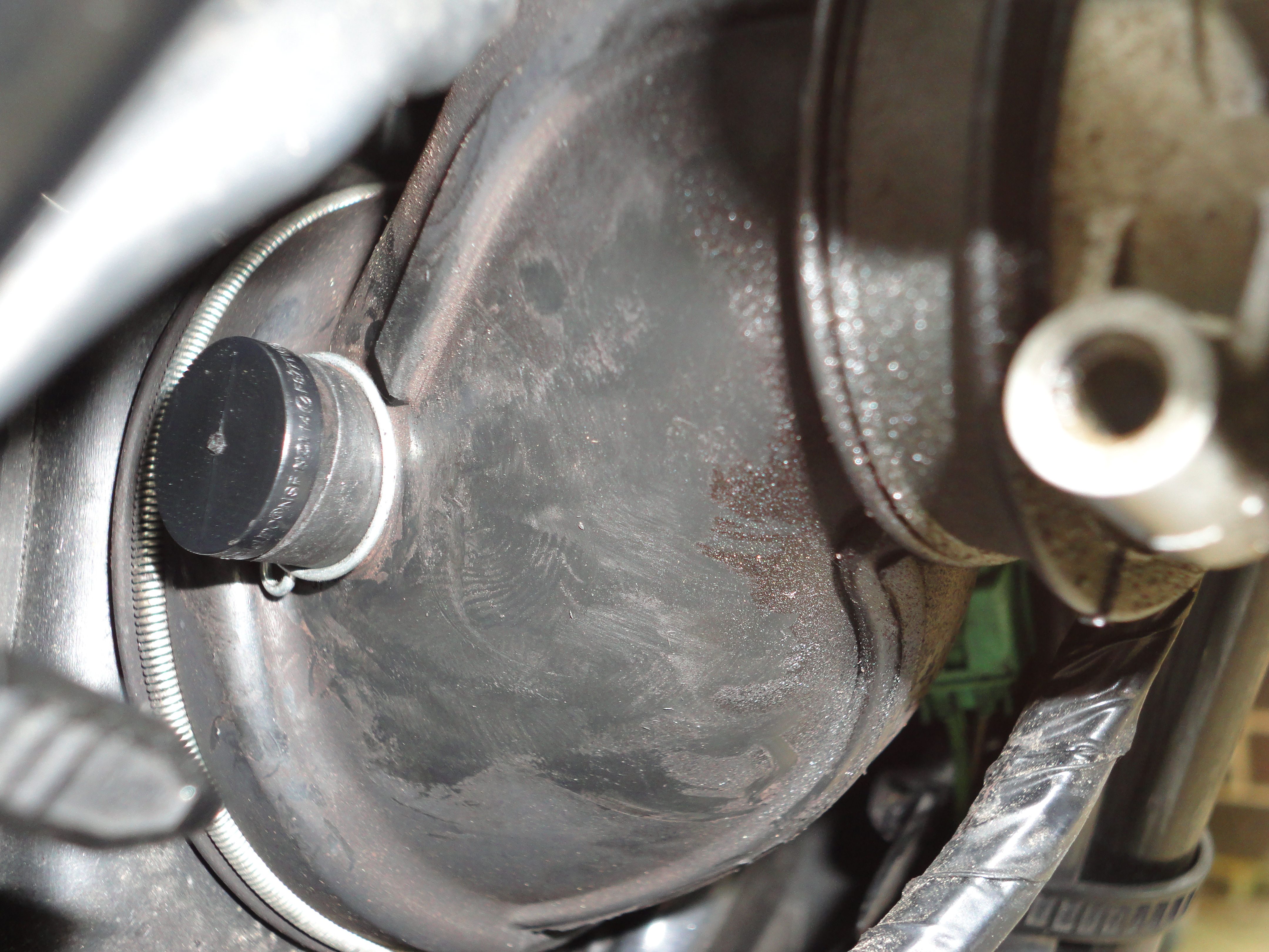 I originally didn't have much luck finding a plug, so I simply used
the existing clamp to hold two layers of plastic from a zip-lock
baggie over the port. After just under 600 miles my impromptu seal was
still intact, but I stopped by a Home Depot and bought a 1/2 inch
flanged black plastic plug which fit perfectly and looks for all the
world like it belongs there. You can snag the same plug from Amazon -- a SharkBite UP514A, 1/2-Inch Plug
I originally didn't have much luck finding a plug, so I simply used
the existing clamp to hold two layers of plastic from a zip-lock
baggie over the port. After just under 600 miles my impromptu seal was
still intact, but I stopped by a Home Depot and bought a 1/2 inch
flanged black plastic plug which fit perfectly and looks for all the
world like it belongs there. You can snag the same plug from Amazon -- a SharkBite UP514A, 1/2-Inch Plug
Plug Up the Cylinder Head Cover
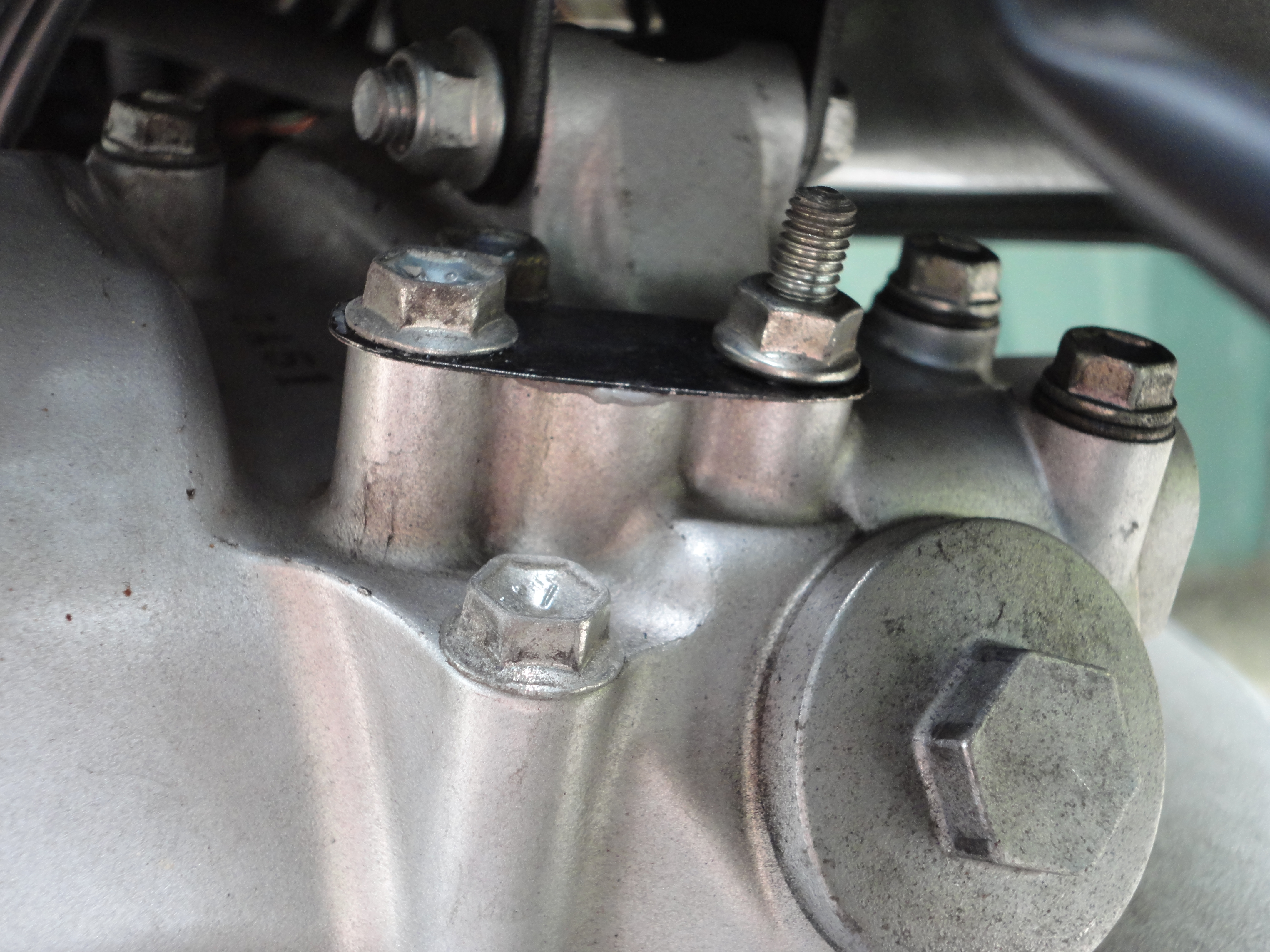 The cylinder head cover is another matter entirely. There will be
significant heat and positive pressure, with moments of negative
pressure as well. I shaped a bit of sheet metal by tracing the
original PAIR attachment, drilling two holes for the mounting
points. I then put a thin bead of liquid gasket around the hole and
attached my blank. I may augment this with a pair of washers (I used
very thin metal) but it does not appear to be leaking.
The cylinder head cover is another matter entirely. There will be
significant heat and positive pressure, with moments of negative
pressure as well. I shaped a bit of sheet metal by tracing the
original PAIR attachment, drilling two holes for the mounting
points. I then put a thin bead of liquid gasket around the hole and
attached my blank. I may augment this with a pair of washers (I used
very thin metal) but it does not appear to be leaking.
Plug Up the ECU
 There are a number of threads regarding how to properly "trick" the
ECU into seeing a false PAIR valve. The original PAIR valve has a
resistance of 22 Ohm. A 12V load on a 22 Ohm resistor would require
the resistor to be capable of dissipating more than 6 Watts of power
without burning up. Automotive resistors do exist with these
attributes, but can be expensive.
There are a number of threads regarding how to properly "trick" the
ECU into seeing a false PAIR valve. The original PAIR valve has a
resistance of 22 Ohm. A 12V load on a 22 Ohm resistor would require
the resistor to be capable of dissipating more than 6 Watts of power
without burning up. Automotive resistors do exist with these
attributes, but can be expensive.
I decided to go with two 1 KOhm 1/4 Watt resistors in parallel. They are well within their power dissipation rating at 12V, and the resulting 500 Ohm of resistance is enough to still make the ECU consider the device to be present and functional.
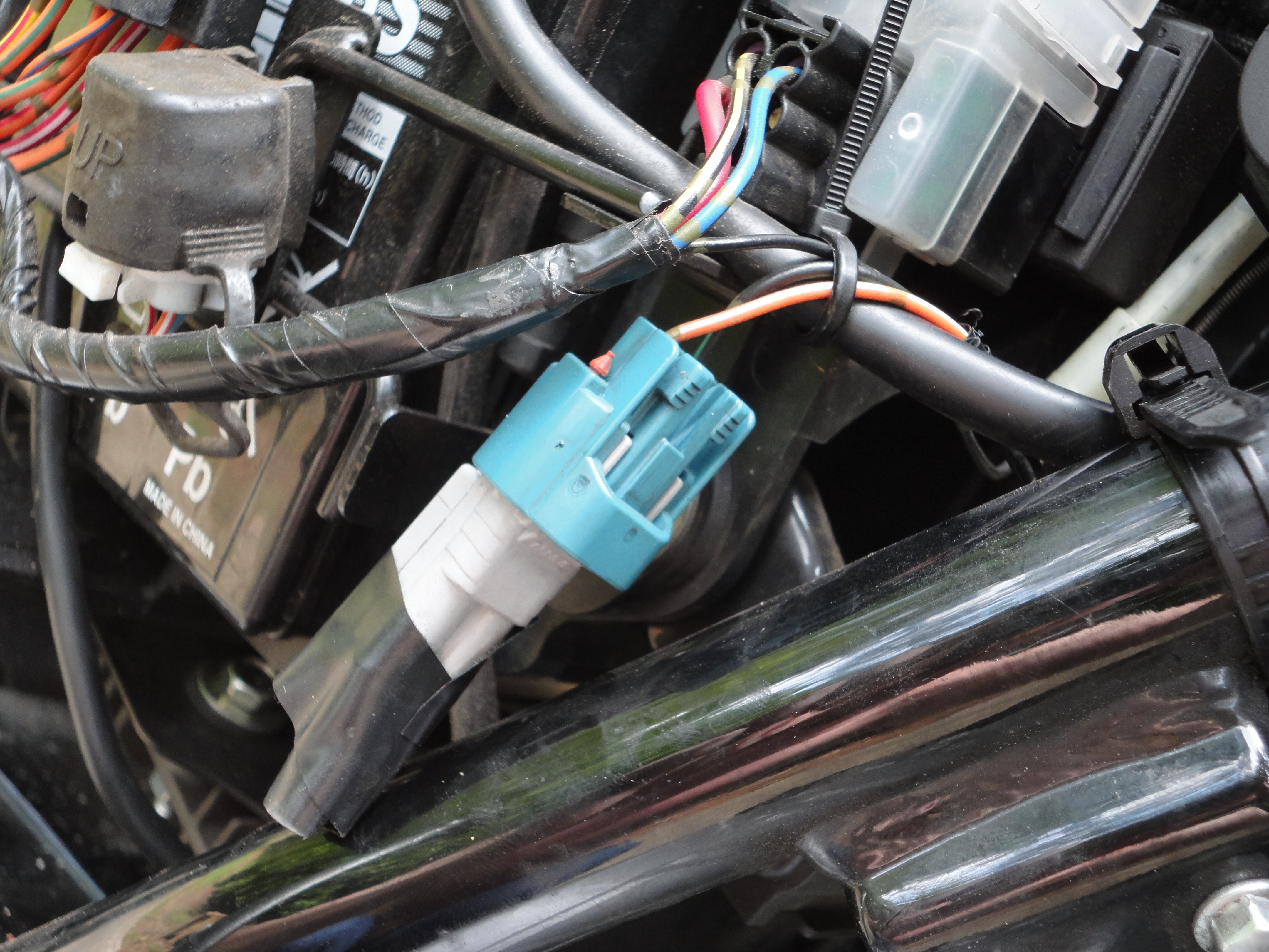
I purchased the minimum order of the 2P090WP-TS-M plug from
Eastern Beaver (third one down the page, but verify the model
number), and soldered my two resistors directly to the two terminals
before assembling the plug and wrapping the bare resistor leads in a
bit of electrical tape.
I zip-tied the resultant dummy load into a protective area under the right-side cover, next to the fuse box.
Done
That's it. Fire up the engine and check that the FI light stays off. Rev the engine once or twice and check that there's no obvious blow-out on your cylinder head blank.
As an added bonus I've found that after this modification there was a reduction in instances of "cold-stop-stalls" that the TU is slightly infamous for, though I've hardly had enough time to consider this change in behavior as anything other than a blip of data.
If you enjoyed the photos, here's the entire album. You can read more about the mods I've made to Tux on my motorcycle projects page
Changelog
- 2023-09-25 updated to local photos
- 2014-08-30 added photos, links, etc.
- 2014-08-26 initial write-up. TODO, add pictures and Eastern Beaver links to the correct plug.